Einführung
Für diejenigen, die von dem Projekt Me P.1112 noch nicht viel gehört haben, hier eine kleine Einführung.
Das Konstruktionsbüro der Fa. Messerschmitt in Oberammergau hat sich in den letzen Kriegsmonaten fast ausschließlich mit den Entwürfen strahlgetriebener Flugzeuge beschäftigt. Prof. Messerschmitt hatte erkannt, dass den Düsentriebwerken die Zukunft gehörte, was sich ja nach dem Krieg auch bewahrheitete.
Unter einer Projekt-Nummer entstanden meist verschiedene Entwürfe, teilweise auch ganz unterschiedlicher Flugzeugkategorien. Als Beispiel beinhaltet die Reihe Me P.1101 Jäger, Bomber und Zerstörer. Interessant ist in diesem Zusammenhang, dass sowohl die Projektreihen Me P.1101, P.1106, P.1110, P.1111 und P.1112 einstrahlige Jäger beinhalteten. Vielfach wird behauptet, dass das Projekt Me P.1112 die Zusammenführung der Vorstudien aus den anderen genannten Projekten war.
Ich denke, das kann man tatsächlich so sehen.
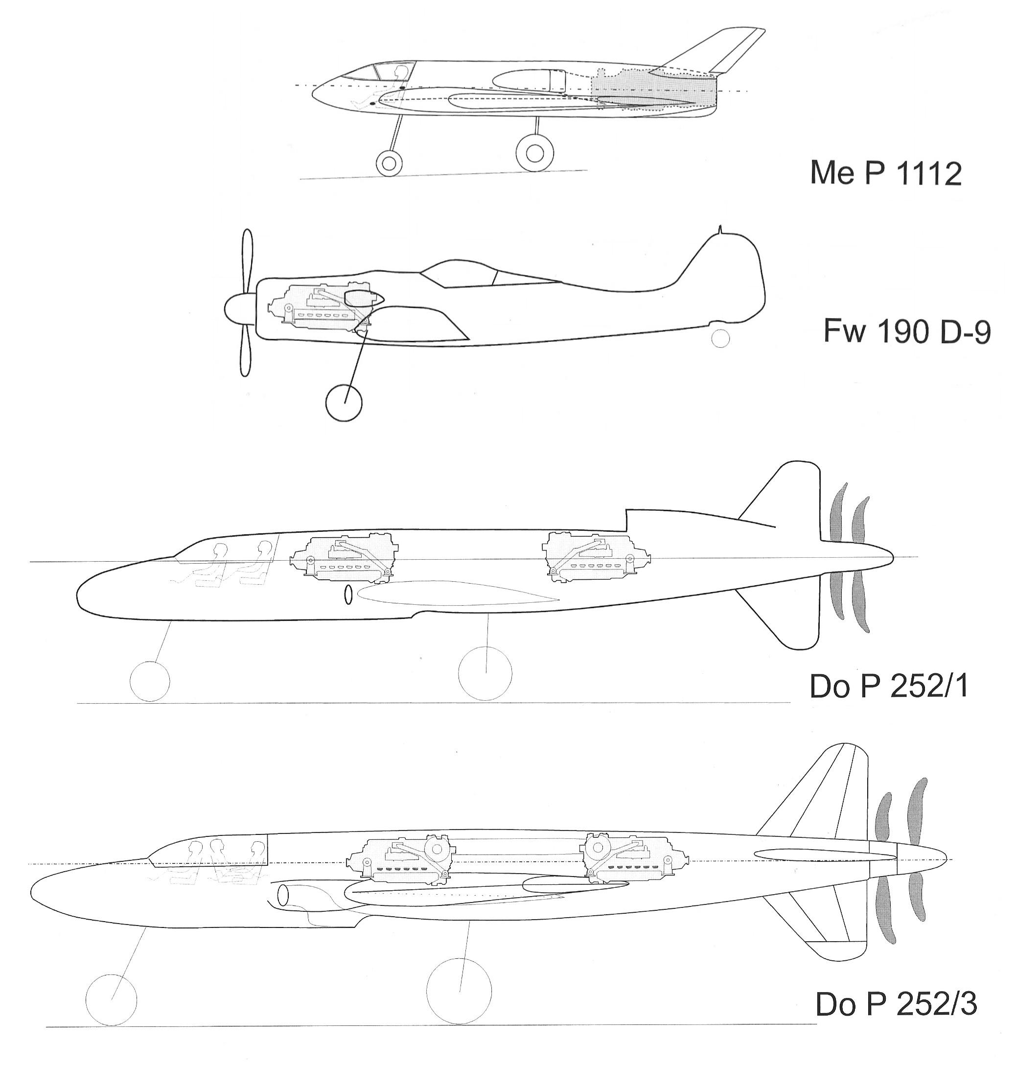
Der einstrahlige Jäger, besser noch „Leichtjäger“, war in Anbetracht der Kriegslage sicher die einzige Möglichkeit, (zumindest theoretisch) noch größere Mengen schnelle Jäger produzieren zu können. Andere Flugzeugfirmen hatten noch auf Propellermaschinen mit Kolbenmotoren gesetzt, leider auch hier mit dem Problem, dass solche Motoren wie der Jumo 222, der BMW 803 oder gar der As 413 alle noch ein Stück von der Serienreife entfernt waren. Deshalb setzte man zum Teil auch auf existierende Baumuster wie DB 603 oder Jumo 213, dann allerdings in Doppelanordnung hintereinander mit zwei koaxialen Wellen und zwei gegenläufigen Schub-Propellern (mit sichelförmigen Blättern) im Heck. Geschwindigkeiten von erstaunlichen 900 km/h und sogar etwas darüber, sollten erreicht werden…. Aber um welchen Preis! Die Maschinen (z.B. Do P.247, P.249, P.252) waren gut doppelt so groß wie z.B. eine Me 109 und bald dreimal so schwer. Entsprechend hoch wären auch die Fertigungsstunden, die benötigte Menge an Materialien und die Kosten gewesen.
Das hatte auch das Reichluftfahrtministerium (RLM) erkannt und entsprechende Programme für Leichtjäger mit Strahlantrieb formuliert. Messerschmitt hatte zusätzlich erkannt, dass bei den damals noch bescheidenen Leistungen der Triebwerke hohe Unterschall-geschwindigkeiten (um 1100 km/h) nur erreicht werden konnten, wenn man Flugzeuge mit einem möglichst kleinen Rumpf-Querschnitt konstruiert und auch sonst alles vermeidet, was aerodynamisch stört, also zuviel Widerstand bietet. Dazu zählte auch aerodynamische Feinarbeit hinsichtlich Blechstöße und Niete.
Hier nun ist der Entwurf MeP 1112 nahezu unschlagbar. Der Rumpf hatte im wesentlichen einen Kreisquerschnitt und nach meinen Kalkulationen betrug er kaum mehr als 1 m, d.h. nur wenig mehr, als einsitzige Segelflieger aufweisen. Man kann dies auch an der mit ca. 600 mm Breite recht schmalen Hautarmaturentafel erkennen. Die Kanzel war voll in den Rumpfquerschnitt integriert (eingestrakt) und selbst die Triebwerks-Lufteinläufe kamen ohne eine Rumpfverdickung in Form irgendwelcher Lufthutzen aus. Naturgemäß ist es dann schwierig, die an den Rumpfseiten mit über 1000 km/h vorbeiströmende Luft dazu
zu bewegen, in das Flugzeug hinein –in Richtung Triebwerk- zu fließen. Einmal muss man die träge Luft dazu bringen, überhaupt seine Fließrichtung zu verändern und zum anderen muss man auch noch dafür sorgen, dass die Strömung laminar (also anliegend und in „geordneten“ Strömungspfaden) bleibt. Ein Ablösen der Strömung hätte zu Turbulenzen und damit zu großen Widerständen und vor allem für zu wenig Luft für das Triebwerk geführt. Das Büro Messerschmitt ließ sich dazu einen rampenförmigen Lufteinlauf einfallen (siehe auch Kapitel „Lufteinlauf“), der auf seinem Weg zwischen Rumpfaußenhaut und Triebwerk zwei Schlitze aufweist, durch die Luft abgesaugt wird. Wenn die Schlitze schmal und aerodynamisch richtig
gestaltet sind, und der abgesaugte Volumenstrom richtig bemessen ist, dann kann man auf diesem Wege die Grenzschicht zwischen der Einlaufbeblechung und der schnell strömenden Luft absaugen. Dies soll dann dazu führen, dass der Luftstrom tatsächlich laminar bleibt und der Kontur des Einlaufes folgt. Grenzschichtabsaugung ist auch heute noch ein probates Mittel, um Turbulenzen z.B. an den Tragflächen zu verhindern. Das Gebläse, welches die Luft absaugte, lag direkt vor der Turbine und wurde vermutlich direkt von der Turbinenwelle angetrieben. Der Literatur zufolge „kostete“ diese Gebläse ungefähr 200 PS an Leistung.
Im Zusammenhang mit den Problemen, möglichst geringe Strömungswiderstände zu erhalten ist auch die von deutschen Aerodynamikern gefundene Flächenregel zu sehen. Die Flächenregel besagt ja, dass die Widerstände dann besonders klein sind, wenn sich die Querschnittsfläche eines Flugzeugs über die Länge möglichst wenig ändert und wenn, dann auch nicht abrupt. In diese Betrachtung waren alle Querschnitte einzubeziehen, also auch Tragflächen, Triebwerke, Zusatztanks u.s.w.
Nach dem Krieg entstanden auf Basis dieser Regel die taillierten Rumpfformen, die ihren Querschnitt in genau dem Bereich verringern, in dem die Tragflächen zu einer Querschnittsvergrößerung beitragen.
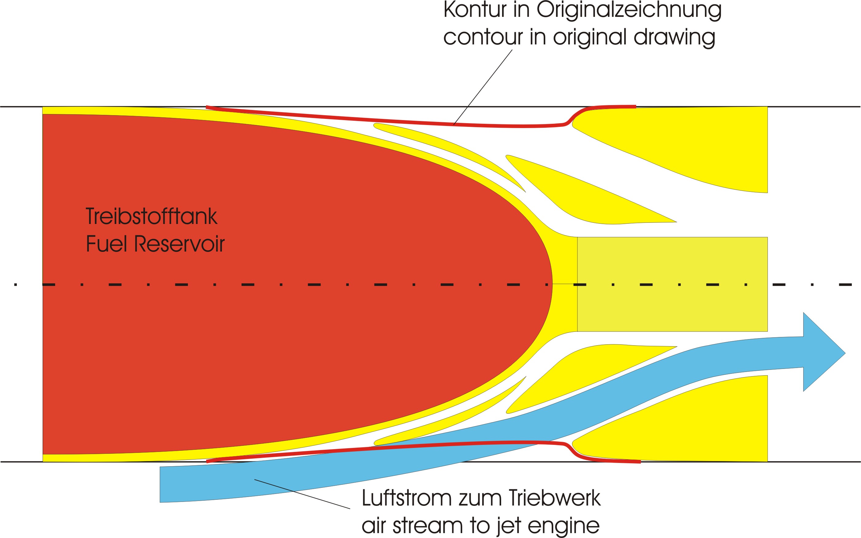
Von de MeP 1112 wurde mehrfach behauptet, dass auch sie der Flächenregel gehorche, weil man im Rumpfmittelteil in der Draufsicht so etwas ähnliches wie eine Einschnürung zu erkennen glaubt. Tatsächlich aber handelt es sich hier nur um eine annähernde Kontur, die die Einlaufelemente quasi umhüllt. Ich habe diesen Einlauf mit dem 3D-Programm nachempfunden und genau von oben gesehen dargestellt. Die zusätzlich hinein gezeichnete rote Kurve entspricht dabei ziemlich genau der Kontur in der Messerschmitt-Zeichnung (wobei man damals im Entwurf ohnehin nur die Kontur angedeutet hat und nicht exakt konstruiert).
Die Einlaufkontur im Horizontalschnitt / The Shape of Air Inlet in Horizontal Section
Introduction
For those who haven’t heard much about the project MeP 1112 here a little introduction.
In the last month of the Second World War the design bureau of Messerschmitt in Oberammergau nearly solely worked on aircrafts which should be powered by jet engines.
Prof. Messerschmitt had recognised that jet engines would be the future what proved to be true after the war.
Belonging to one project number of Messerschmitt there were often several drafts partly of very different aircraft types. As an example the Project MeP 1101 consists of drafts for bombers, for ground attack aircrafts and for fighters.
In this context it is of interest that the project series 1101, 1106, 1110, 1111 and 1112 included single jet engine fighters. Often it is said that the MeP 1112 was the junction of all the other studies and I think that is true.
The single jet engine fighter or better the “fighter light” was in consideration of that stage of war the single possibility (theoretically) to produce bigger quantities of high velocity fighters. Other aircraft design bureaus still focussed on airscrew and piston engine powered aircrafts, unfortunately here with the same problem that such engines like Jumo 222, BMW 803 or As 413 were far away from series production. Due to that they partly used existing types as DB 603 or Jumo 213, but in tandem installation with two co-axial shafts and two counter-rotating airsrews (with crescent-shaped blades) in the rear. Speed of astonishing 900 km/h or a little bit above should have been achieved……. but for what a price?! The aircrafts (e.g. DoP 247, P 249, P 252) had more than the double size of a Me 109 and they were nearly three times heavier. Correlative high the manufacturing hours, the needed material and the costs would have been.
This also was recognized by Ministry for Aviation (RLM) and they framed corresponding programs for small fighters with jet engines. Messerschmitt additionally recognized, that due to the poor power output of the first jet engines high sub-sonic speeds (about 1100 km/h) could only be achieved if they designed aircrafts with a small cross-section of fuselage and if they avoided everything which disturbs good aerodynamics,i.e. gives too much resistance. Among this it counts on aerodynamic precision work concerning sheet joints and rivets.
Herein the draft of MeP 1112 is unbeatable. The fuselage fundamentally had a circular cross-section and by my calculation it has hardly more than 1 metre in diameter, i.e. only a little bit more than modern single-seat gliders have. This can also be seen by the relative small instrument board with a width of approx. 600 mm (24 inch). The canopy was fully integrated in the fuselage and the air intakes didn’t need any enlargement of cross-section in form of hoods. Naturally it is difficult to force the air, which flows with 1000 km/h along the fuselage, into the ducts leading to the engine. On one hand it is the task to change the direction of the inertial air stream on the other hand to keep the air flow laminar (i.e. close to the fuselage sheeting an in “well-regulated” paths). A flaking of flow would have resulted in turbulences and with this in an increase of resistance and above all to a severe lack of air for the engine.
The Messerschmitt bureau came up with the idea of a “ramp air intake” (see chapter “air intake”), which has two slots on the way between fuselage surface and engine which are designed to suck away a portion of the air. If the slots are narrow and aerodynamic correctly dimensioned and the sucked air stream is correctly determined then it is possible to suck away the boundary layer between the sheeting of the air intake and the rapidly flowing air. This should effect in a really laminar air flow and in following the shape of the air intake. Suction of boundary layer is a proven mean to avoid turbulences at wings today. The blower which should suck the air was lying adjacent to and in line with the engine and was probably driven by the engine shaft directly. As reported in literature this blower “costs” a power of approx. 200 PS.
In connection with the problems to achieve flow resistances as low as possible has to be seen the “Flächenregel” (area rule) which had been found by German scientists. The area rule says that the resistances are notably small, when the area of the cross section of an aircraft doesn’t change much over the length and if so then not abruptly. One has to take into account any cross sections i.e. wings, engines, outer fuel tanks and so on.
After WWII waisted shapes of fuselages have been designed on base of this “area rule”. It had been claimed some times in literature that the MeP 1112 had been designed according to the area rule too, because one can see something like a waisting in top view. But this is a rough contour line only covering the elements of the air intake.
I have sketched this air intake (horizontal section) by CorelDraw. The additionally drawn red line
corresponds nearly exactly with the contour which one can see in the Messerschmitt drafts (in which the contour seems not to be really determined but sketched only).
Of interest are also the very short time spans in which such drafts had been done. So they had engaged in the projects MeP 1106, P1110, and P1111 in January and February of 1945. Not to forget the MeP 1101 which existed as a prototype at this time. For this aircraft they were waiting for a jet engine only.
Today it seems to be unbelievable that a factory like Messerschmitt didn’t get an engine. Well, the planned engine HeS 11 had not reached the maturity phase, but that it shouldn’t be possible to get only one of the Jumo 004 engine of which more than 6,000 pieces had been produced and which had been built mainly into the Me 262, that is really astonishing!
Anyway, the draft or better the drafts of the MeP 1112 had been drawn in March of 1945 and the draft of the “stop point” namely of the MeP 1112-V1 is dated to the 30th of March 1945. One has to comprehend that already on the 29th of April the American troops ran over the Messerschmitt Works in Oberammergau and only 8 days later WWII ended by capitulation of Germany.